Flare seals reduce the amount of purge gas needed to keep the flare system free of air which is a potential explosion risk. Both types of seals are installed below the tip. Molecular or buoyancy seals reduce the purge gas more but are more expensive to install. Velocity seals cost less to install but require more purge gas.
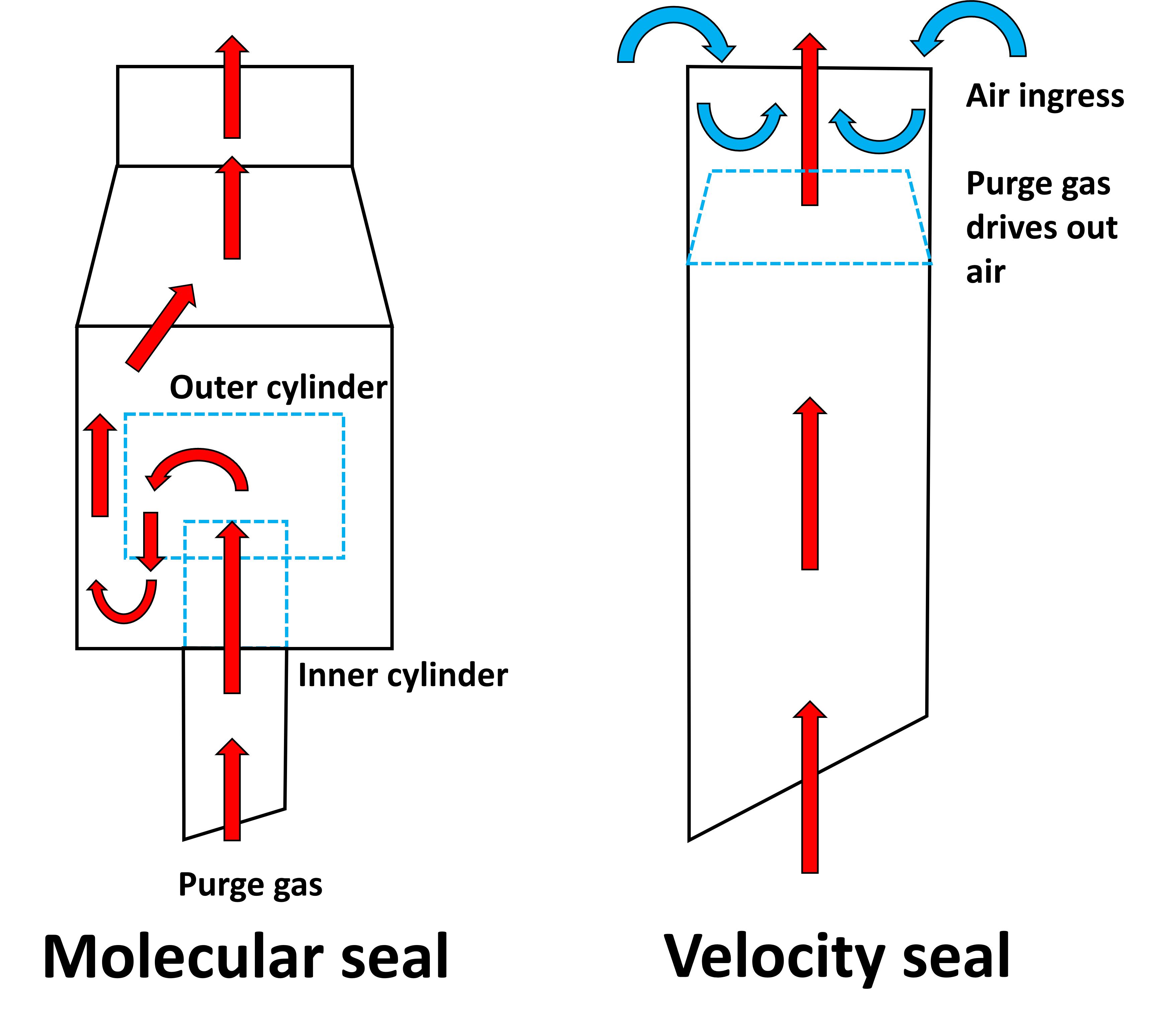
Molecular or buoyancy seals employ a tortuous path technology and the density difference between air and the purge gas to prevent air backflow. The purge gas tends to accumulate in the high or low spots, depending on whether it is lighter or heavier than air, and form a seal.
Velocity seals require the purge gas to flow through a reduced diameter throat so that its velocity increases, preventing air ingress past the throat and entraining any air accumulated above the throat out of the tip.
Indicative performance characteristics:
Advantages
Both types of seals effectively reduce purge gas relative to a flare without a seal, but offer trade-offs in capital expense and performance. A molecular seal will cost more to install and less to operate and emit less than a velocity seal
Limitations
Seals require regular monitoring to insure that drain lines for condensed steam flow freely. Plugged drain lines, whether due to mechanical damage or freezing, impair flare performance
Velocity seals may not be possible for larger (24” or greater) flare lines
Case study
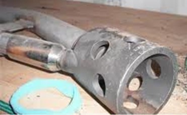
Cracks at the weld joint of the molecular seal drain line
Reproduced from an original article in Optimizing Flare Operation Through Proper Design – Chemical Engineering | Page 1 (chemengonline.com)
OPTIMIZING FLARE OPERATION THROUGH PROPER DESIGN
By Hyunjin Yoon, SK Energy | October 1, 2015
Freezing of the molecular seal drain line.
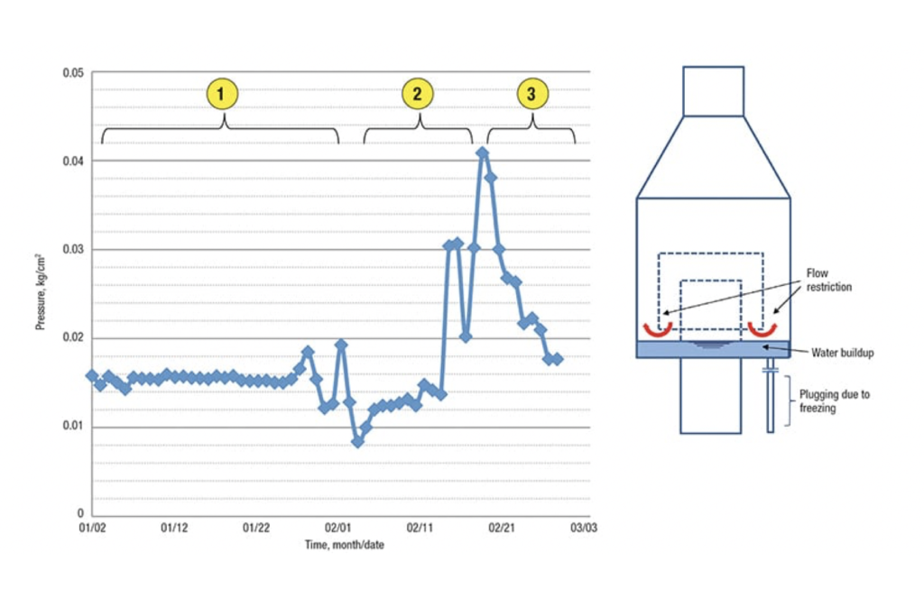
In this case, freezing of the molecular drain line caused a pressure increase on the flare header, and it was beginning to approach the design limit. All of the process units that feed offgas to the flare had to prepare for potential shutdown (since none would be allowed to operate without proper waste gas disposal). When analyzing the pressure data on the header, it was found that the pressure had been relatively static for nearly a month and a half, although a slight upward trend was barely noticeable until it suddenly increased sharply (Figure 3).
FIGURE 3. The graph (above left) shows the pressure profile of a flare header (which remained fairly static at first, but then rose suddenly). The figure (above right) shows the water buildup in the flare molecular seal. As the graph indicates, water was building up in the molecular seal drain line during the month of January (the portion of the graph labeled 1). An abrupt increase in the flare header pressure during the middle of February (graph segment 2) indicated the presence of plugging due to freezing. By March, the pressure had returned to normal, once the ice had been cleared (graph segment 3)
FIGURE 3. The graph (above left) shows the pressure profile of a flare header (which remained fairly static at first, but then rose suddenly). The figure (above right) shows the water buildup in the flare molecular seal. As the graph indicates, water was building up in the molecular seal drain line during the month of January (the portion of the graph labeled 1). An abrupt increase in the flare header pressure during the middle of February (graph segment 2) indicated the presence of plugging due to freezing. By March, the pressure had returned to normal, once the ice had been cleared (graph segment 3)
The abrupt spike shows that there was no gradual increase; rather, the drain line was plugged. If the pressure had been rising slowly and continuously then steps could have been taken to shut down all related process units feeding the flare. We had two options — one was to prepare an unscheduled plant shutdown, and the other was to clear the pressure buildup problem over the course of one week while the system was still operating. However, over the course of the week, the pressure could have exceeded the design limit. Unfortunately, many operators typically have no experience dealing with drain-line plugging resulting from icing. The molecular seal drain is provided to drain water that is created during operation by steam condensation. Drain line plugging becomes apparent when the drain valve is open and no water flows at all. When operators fully understand the proper function of the molecular seal system, they will respond immediately to a pressure buildup in the header by checking the drain water to discover or rule out a blockage from ice formation. But in this case, no one at the facility had a clear understanding about the plugging of the molecular seal drain line, once the header pressure began increasing. During the cold winter season, condensation will occur at both the center steam-injecion point and the upper steam-injection point at the flare tip. The center steam helps lift the flame and the upper steam enables smokeless flaring. Small parts of the center steam will condense when the shell of the flare tip is cool enough and the atmospheric temperature falls. The condensate drips down along the inside shell of the flare tip and accumulates at the bottom of the molecular seal drum. If there is no proper drainage, then this condensed water can build up, freeze and eventually block the offgas route. Upon making a close inspection all along the drain line through the stack height, there was one area (around a 1-m span out along the drain line) where the insulation had slipped away near the bottom of the thermal-expansion loop. The steam tracing was still operating, but because the insulation had slipped on a portion of it, the bare piping was still prone to icing during cold winter days (freezing temperatures of –10oC were common). In order to melt the ice buildup, the low-pressure steam was serviced through the drain line bottom connection. However, we had to spend more than two days clearing the plugged piping while the flare was still operating. Due to the limited access near the flare tip during operation, the damaged insulation could not be repaired during this effort, so we had to rely on intermittent service of steam to periodically remove the ice buildup throughout the winter season. We had to wait to repair the insulation during a scheduled turnaround, and had to spend more than $0.8 million for scaffolding work all along the 120-m stack height to access the right point. Considering the importance of the molecular seal drain line, it is important to prepare and maintain vertical piping insulation carefully…