Active Laser SpectrometrySpectrometry is the observation and measurement of wavelengths of light or other electromagnetic radiation. Once a range of wavelengths, or a spectrum, for a gas mixture has been measured, by… Learn more… uses a tuneable laser to monitor atmospheric pollutants, including methane. The laser is directed into the area of interest and back scatter creates by aerosols and pollutants negates the need for a reflector.
Systems can operate over large distances (up to 1km in real time) and differentiate between multiple plumes and sources, but may be limited for field applications because of the size and complexity of the equipment.
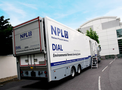
DIAL (Differential Absorption LidarLidar is a method for determining ranges (variable distance) by targeting an object with a laser and measuring the time for the reflected light to return to the receiver. LiDAR… Learn more…) is an example of this type of technology. DIAL emission measurements can be used to determined relative flare combustion efficiency and absolute quantification of emissions.
A laser source of tuneable wavelength is transmitted over the measurement region. A small fraction of this light is scattered back by the aerosols and particulates that are present in the atmosphere; this is collected with a telescope and a fast, sensitive detector. There is no requirement to scatter off a feature, such as the ground or a mirror.
The extent of the absorption is known from accurate laboratory data and this enables the concentration, and spatial distribution, of the atmospheric pollutants to be determined. This is combined with wind information to provide emission data. When emission measurements are combined with data on the flow and composition of the hydrocarbons supplied to a flare, various aspects of flare performance can be determined including combustion efficiency.
Main Image Courtesy of the National Physical Laboratory UK
Advantages
Direct measurement of the emissions from a flare with no assumptions about flare combustion efficiency or the operating conditions of the flare. The measurements can therefore be used to test and validate emission estimates and other methods. When calibrated against national gas standards the method can be fully traceableWherby a measurement is calibrated to a reference standard and when the uncertainties of th calibration are insignificant compared to the uncertainties arising from random effects or from a limited number... Learn more...
Several different species relevant to flares can be measured simultaneously including methane, ethane and general hydrocarbons separately, and therefore measure the different levels of unburnt hydrocarbons in a flare’s emission. This allows a direct calculation of the combustion efficiency of the flare if the composition and flow rate of the gas is known
Measurements are range-resolved and can be used to produce a three-dimensional map of emissions. This means that the location of emissions and plumes can be mapped and spatially separate sources can be identified and quantified. It is possible for the system to differentiate between plumes
This technique removes the need to access them directly. There is no requirement to scatter off a feature (the ground/ mirror etc.)
Limitations
Requires expert operators and is usually deployed for periods of a few days or weeks. It therefore provides a short-term assessment of the emissions at the time of the measurements and is not yet suited to long-term continuous emission monitoring
A typical measurement scan takes 10 to 15 minutes to complete, so any variations on a shorter timescale will not be captured
Currently available systems such as the DIAL facility are very large (17m long, 2.5m wide, 4m high) can make access to some smaller sites difficult. The DIAL system is currently mounted on a heavy vehicle
Although emission measurements can be made in most weather conditions, including rain and snow, there are some conditions where they are not possible, in particular very light winds (<0.5m/s) and heavy fog
Quantitative data requires access to metered flow rates and/or meteorological data
Case study
Flare measurements were performed at an onshore facility which receives gas from oil fields and treats it according to export specifications. The primary aim of this campaign was to determine the emission rates of methane, ethane and NOx from three flares on the plant.
The flow rate and composition of the gas to the flare was recorded during these measurements meaning that the flare combustion efficiency could be calculated using the following formula:
Combustion Efficiency (%) = [1 – (Carbon emitted/Carbon in flare gas)] x 100 Where carbon refers to the number of carbon atoms in hydrocarbon form.
This equation is valid under the following assumptions:
This flare is part of the plant system to remove low pressure gas from the process stream under emergency conditions. The flare is continuously purged with nitrogen to prevent oxygen building up in the flare system. This flare burns continuously at low flow. This flare was measured ‘as found’
The measurements of this flare showed high levels of methane emission compared to the other species, with the flaring efficiency less than 50%. At this level the assumptions in the calculation of flare efficiency are not valid, particularly the final two assumptions.
The main reason for the low combustion efficiency was that the combustible part of the flare gas was approximately 50% of the volume, and this is further diluted by air drawn around the base of the flare.
The maintenance flare is an open ground level flare. This flare is designed to receive gas during routine maintenance on the plant. This flare was measured under normal conditions, where only the pilot burners were lit (‘flare off’), and under an increased flow condition with the main burners were lit (‘flare on’).
In all cases the maintenance flare was measured with the DIAL measurement plane less than 20m downwind of the flare.
This flare showed higher levels of emission during the ‘flare off’ measurements. This suggests that there was a very low combustion efficiency and the possible presence of a leak.
The reported average flows during the ‘flare-on’ measurements were 90 Sm3 /hr. By combining the DIAL emission measurements with the gas composition analysed by the site, the maintenance flare efficiency was found to be 99.86 ± 0.02 % during the ‘flare on’ measurements. The destruction efficiency is defined as 1 minus the ratio of the amount of the species measured downwind of the flare to the amount of the species present in the flaring gas (expressed as a percentage).
The gas composition was not analysed during the general hydrocarbon measurements so the average composition measured during the ethane and methane measurements was used for this calculation.
The high pressure flare is an elevated open flare designed to receive the full gas pipeline in the event of an emergency. Under normal conditions the flare is operated under a pilot gas or low flow conditions. This flare was measured ‘as found’ – with only pilot gas flow, and under increased flow flaring conditions.
For all species the high pressure flare ‘as found’ measurements were conducted with the DIAL measurement plane up to 20m downwind of the flare. For measurements of the flare under increased flow conditions the distance from the flare to the measurement plane was up to 100m. The difference between the ‘as found’ and actively flaring measurement distances is due to the physical size of the flare – measurements were not conducted through the visible part of the flame.
Measurements of the flare ‘as found’ were only taken for ethane and general hydrocarbon. The measurements showed that under this condition the emission of ethane and general hydrocarbon was approximately 50% of the ethane and general hydrocarbon flare throughput.
Measurements of the high pressure flare under increased flow conditions determined the combustion efficiency to be 99.73 ± 0.08 %
| Flare |
Indicative Flow rate SM3/hr |
Combustion efficiency % |
Methane Destruction efficiency |
Ethane Destruction efficiency |
General hydrocarbon Destruction efficiency % |
| Flare #1 |
Not available |
<50% |
|||
| Flare #2 ‘off’ |
Pilot only |
<50 % |
|||
| Flare#2 ‘on’ |
~200 |
99.86 +/- 0.02 |
99.88 +/- 0.02 |
99.73 +/- 0.01 |
99.65 +/- 0.22 |
| Flare#3 ‘off’ |
Pilot only |
<50% |
|||
| Flare#3 ‘on’ |
~4000 |
99.73 +/- 0.08 |
99.74 +/-0.09 |
99.64 +/- 0.07 |
99.69 +/- 0.08 |