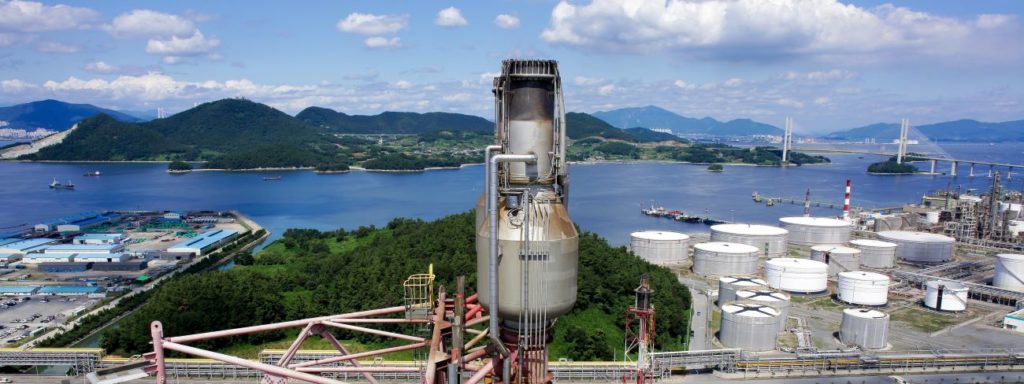
Image courtesy of Zeeco, Inc.® – all rights reserved.
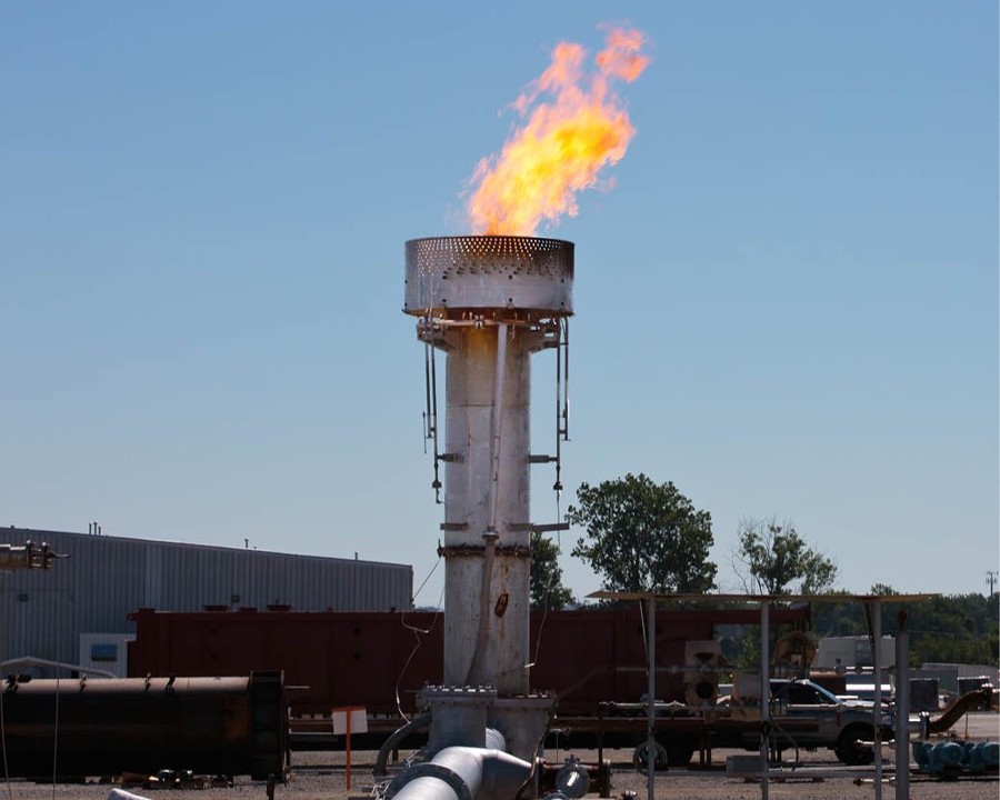
Steam-assisted flare design utilizes steam for efficient air/waste gas mixing and turbulence which provides smokeless flaring while maintaining the desired combustion efficiency.
Advantages
Widely used in the industry where steam is available
Provides smokeless flaring with 98% destruction efficiency provided that the amount of steam is monitored and controlled to maintain the desired combustion efficiency
Limitations
If too much steam is applied, the combustion zoneThe area of the flare flame where the gas and vapours found just after a flare tip combine for combustion. Elevated Flare definitions and calculation methods from 40 CFR 63... Learn more... could be diluted which would reduce the combustion efficiency. As such, optimization of steam injection can be achieved by monitoring hydrocarbon emissions such as using infraredA wavelength just greater than that of the red end of the visible light spectrum but less than that of microwaves. Infrared radiationhas a wavelength from about 800nm to 1... Learn more... cameras, to determine process parameters to improve flare efficiency measurements
It could be a costly option if the local water cost is high
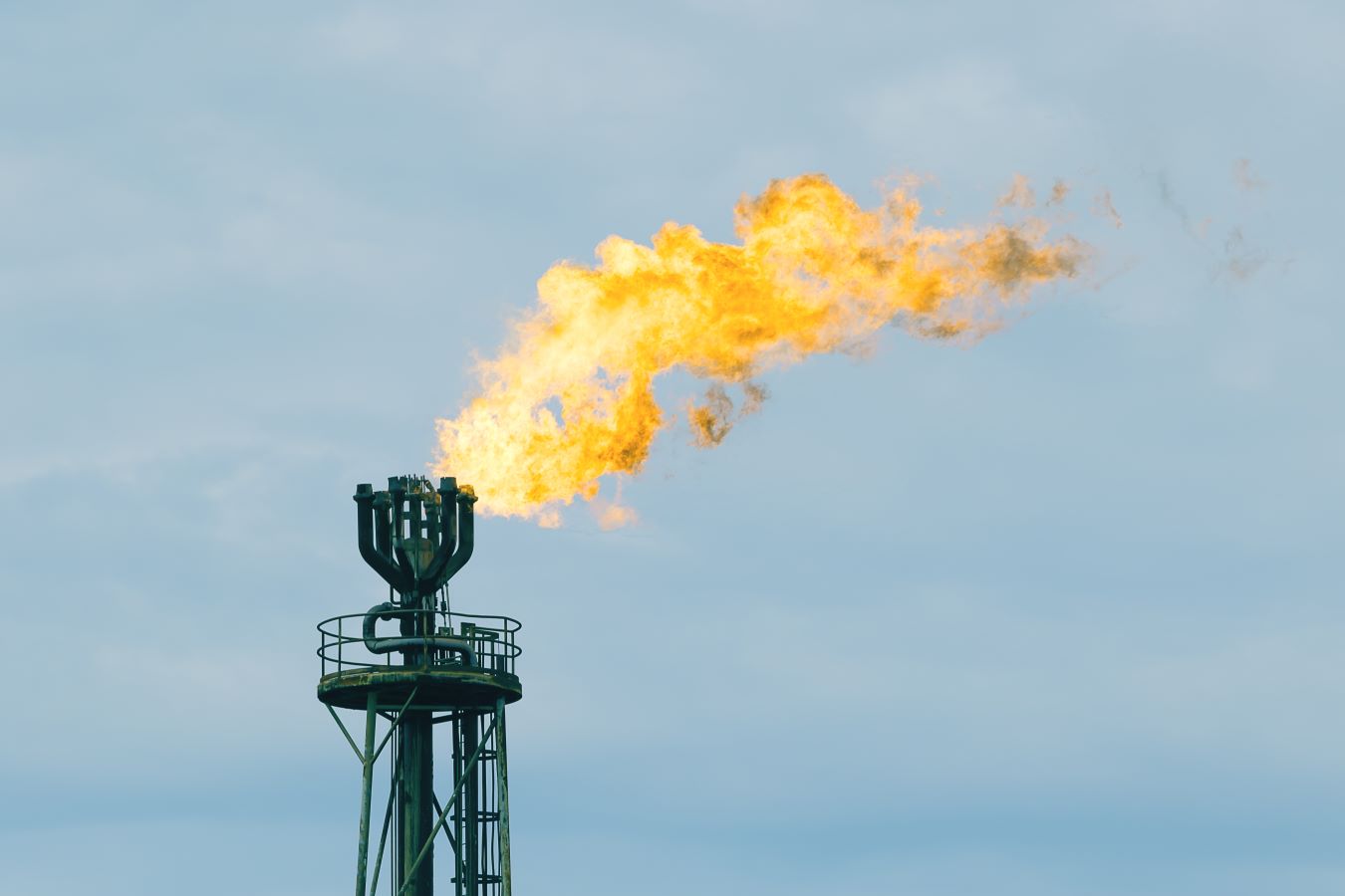
Steam- assisted flares generally produce loud noises that might disturb operators and nearby residential areas
Case study
An industrial flare performance was done on steam-assisted flares organized by the Texas Commission on Environmental Quality, working through the University of Texas.
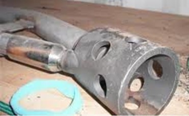
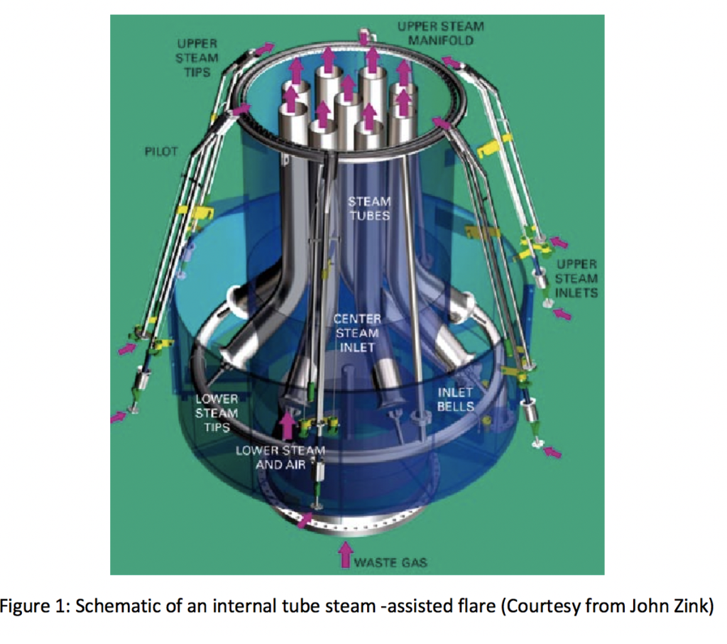
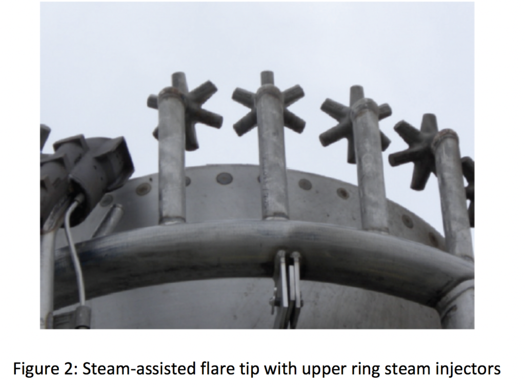
The steam-assisted flare operated with a 36” diameter flare tip. This flare tip has an upper ring for injecting steam around the perimeter of the tip as showed in Figure 2.
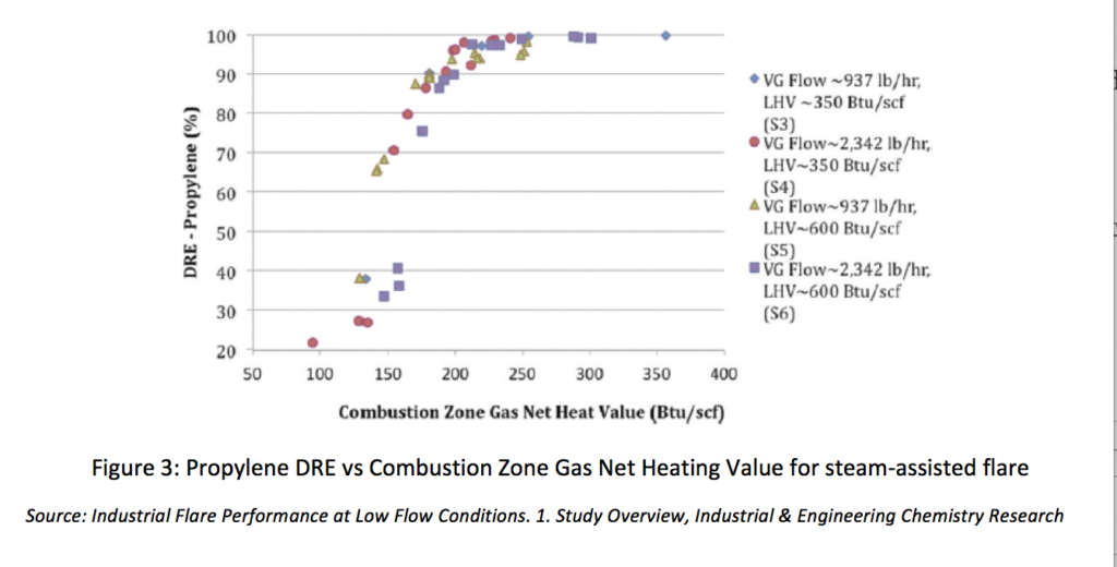
A series of tests was performed on the above steam-assisted flare to explore the destruction and removal efficiency (DRE) for different Combustion Zone Gas Net Heating Values (CZG NHVs) and flaring rates.
Figure 3 shows observed DRE as a function of CZG NHVs. DRE was high (typically > 95%) for CZG NHVs above 250 BTU/scf. Below this value, DRE and combustion efficiency fell off rapidly. The scatter in the DRE values reported in Figure 3 is due to variety of factors such as inherent variability in the flare operation, uncertainty in measurements, and differences in ambient conditions.